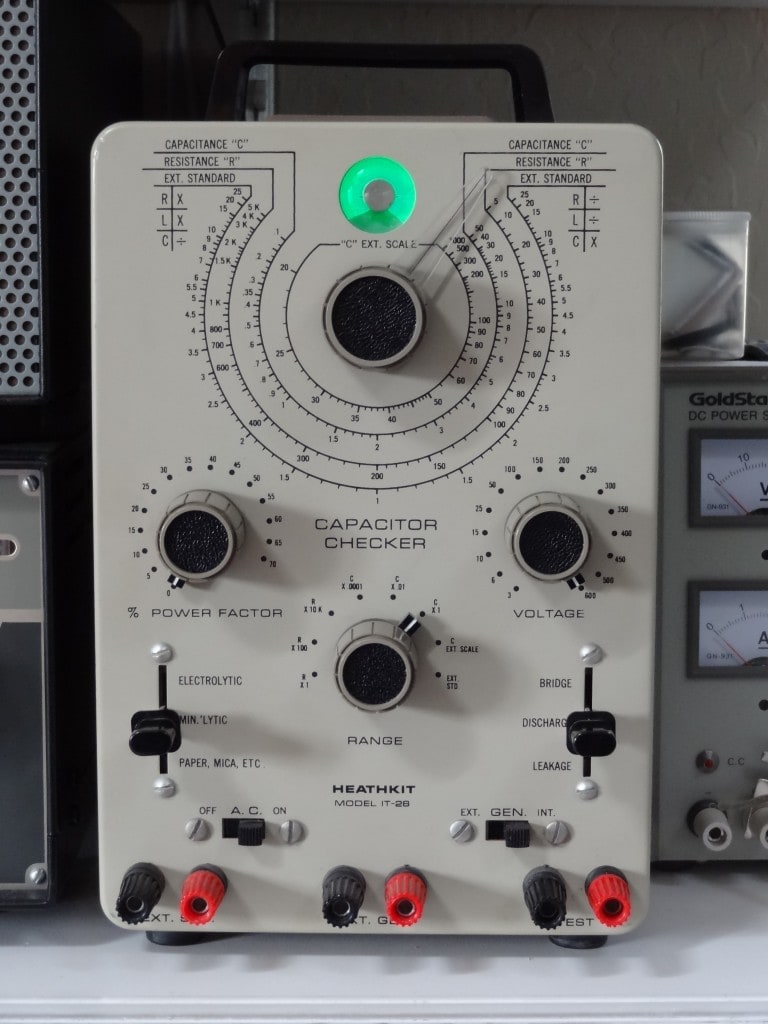
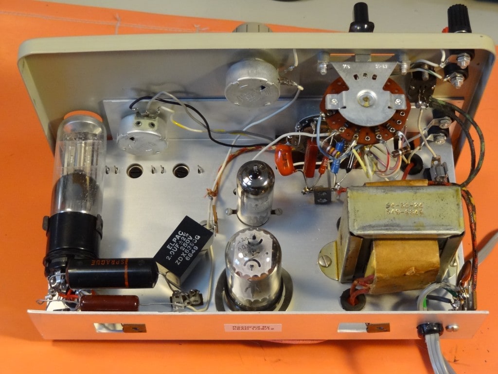
Here I’d like to show those who aren’t comfortable working on test equipment just how easy a Heathkit IT-28 restoration can be. Have a look at the bottom side of the chassis in the photo below. Not too intimidating right? And the Heathkit manual does a good job of explaining the theory.
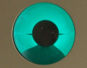
Like most Heathkit gear, this one arrived on my test bench in, well, less than perfect working condition. The eye tube lit up with a nice green glow, but the functions seemed erratic and I could only get the leakage function test to work on a few voltage settings.
If you’ve acquired many Heathkits, you probably already know that about 50% of them contain at least one wiring mistake, and 95% have at least one bad solder joint. I acquired a Heathkit Chippewa Linear a few years ago, and the guy made a nearly fatal wiring mistake. He messed up the regulator circuit consisting of a series string of OA2 tubes, which should have limited the screens on the linear’s 4-400 final output tubes to +800V. Instead, the tube screens got a full +3,000 volts applied. Not to put too fine a point on the observation, this was NOT GOOD.
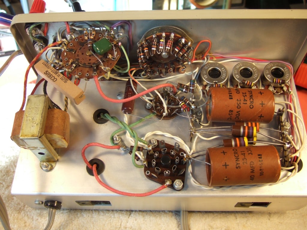
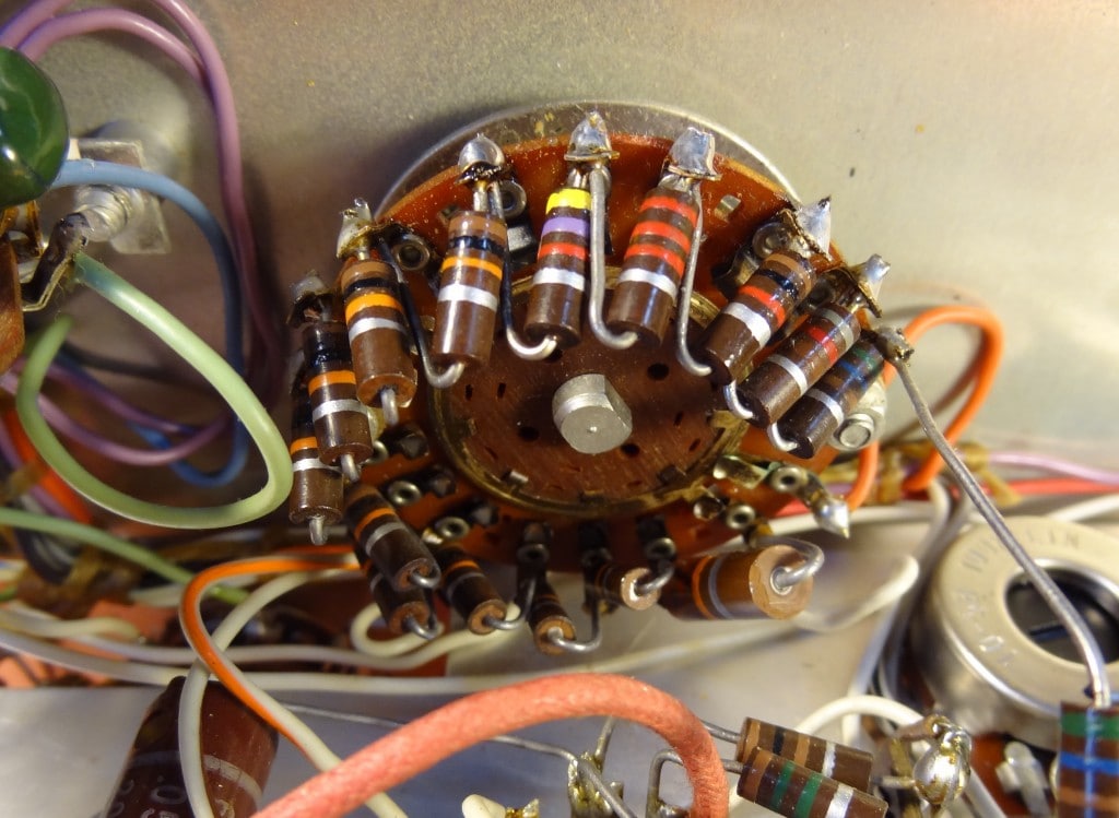
Here is an important restoration tip. Even if you decide not to replace all the old paper capacitors (which I HIGHLY recommend you do), at minimum replace the capacitor in the bridge circuit. It’s easy to spot on the schematic, as all the other bridge components are resistors. Even though my unit was one of the fairly late ones, Heathkit supplied two paper capacitors that were soldered in parallel for one leg of this bridge. That’s right. That last sentence was not an April Fool’s joke. What were they thinking? We’re talking leakage city! And that means an utterly useless, highly uncalibrated bridge. Get those parallel paper caps outta there and don’t ever look back. Put in a modern polystyrene or mylar. You will find this capacitor on the tube side of the chassis near the range switch.
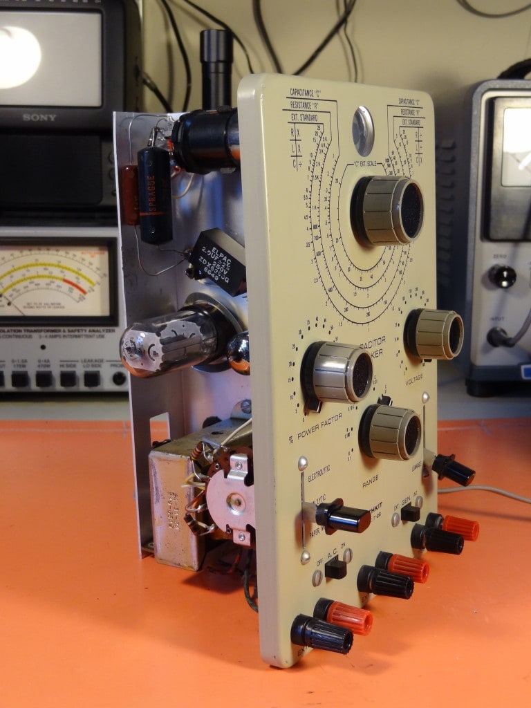
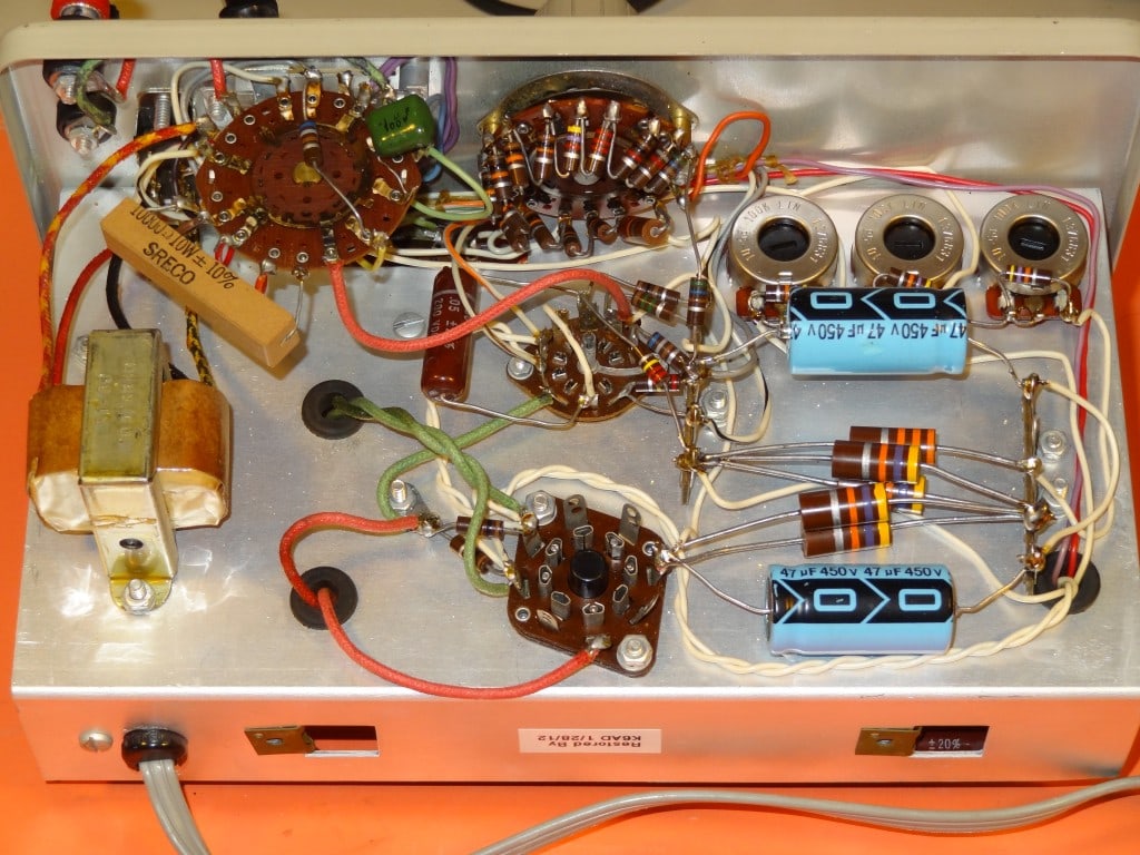
I didn’t alter the design in any way, but some people replace the 6AX4 with a solid state diode to reduce heat. I didn’t do that, as my unit is usually on for only a few minutes to help preserve the life of the eye tube. Arden Allen suggested adding a 330K resistor across each of the power supply electrolytic capacitors (which are in series) to balance the voltage drop across each of them (as was considered good design practice with series capacitors to prevent over-voltage failures).


looking for a manual for this piece of equipment. Could you help me out. Thanks,
George
Manuals are available online. Just Google it.
Great article – many thanks!
Any suggetions on sourcing parts? For example, the two (2) pots (1 Meg, Linear)
for Power Factor and Voltage – suspect 5W/wire-wound); and precision resistors
to calibrate?
Thank you and best regards,
jamaksin – VA and 73
Where can I find the switch knobs for bridge -discharge -leakage ?
Lever switch knobs are the same as used on a Fender Telecaster guitar. Try your local music store or buy on line.
As for the manual I have only find PDF files with 14 pages and not 30 that the manual has..!
Greetings,
I just purchased the heathkit IT-28. Its in good condition on the outside (just dirty) but the inside looks a lot worse, the insulation on the wires is dried out and very stiff., hopefully it was not in water. I must re-wire the unit, what gauge wire is best for that unit?
Another question is that it came with only the Eye tube, the question is for the 6AX7, Is the 6AX7 the same as the 6AX7gtb, I could find plenty of those.
You do super meticulous work.
Thanks for your help,
Vin
the tube is a 6AX4. its a tv damper tube from days of old. (i repaired tv’s for 40 years)
this was a novel way to inexpensivly rectify the around 800vdc in the checker.
bet a microwave oven rectifier would work as an upgrade.
barry
Have had my unit the better part of 20 years, and would not part with it. I have, however, sold my IT-11 and a Paco unit with (if i recall) a regularly shaped tube, the EM84 “magic-eye” tube which had a fluorescent bar which progressed from the bottom of the tube to the top. In my opinion the EM84 was not as attractive as the vintage 6E5 and certainly didn’t look anything remotely like an eye at all.
I came across this site today because I decided that it was finally time for me to do a total recap and be done with the nagging doubt as to whether the readings it was giving me were accurate, and decided to search to see what others had experienced after doing their own recap. Happy to say that my unit works like a champ now.
AND Thomas, the pictures here! One word…WOW! Thomas, you’ve done a wonderful job in both the pictorial representation and in your description(s). Should any owners out there be hesitant about opening it up and doing their own repairs, don’t be hesitant. Jump in there and do it. It will then be good for another 40 years of service on your bench (or in my case, probably my grandchildrens bench 🙂 )
Vin, I have never heard of your tube, the 6AX7GTB, nor have my 4 tube manuals. Are you certain you’re reading the tube correctly (the IT-28 and I believe the IT-11 both call for a 6AX4, NOT a 6AX7)? If so, then yes, certainly xxxxGTB versions of tubes have been compatible with their vanilla versions, excepting of course where metal tubes are called for in a unit where glass would not provided adequate shielding from stray RF, EMF, etc. Take a close look at that tube again to make sure it is a 6AX7 and not the usual 6AX4 tube.
As for the brittle insulation on your wires, that is a direct result of heat inside of the case of the unit. Unless there is a short caused by the insulation breaking, you should not have to worry. Take a gander at each of the wires, individually, and confirm with your meter that they are not shorting to each other. Now, that being said, and if you are up to the job both in terms of time constraints and experience, there is no reason what-so-ever to not do it. Would sure make the unit infinitely more presentable when/if you want to show off the guts. Tell the truth, the more I think about it, the more I think perhaps you should replace them. Would certainly allow you to become intimate with your tester and also bring it back to the same level of safety that codes of those days dictated. I would suggest that if possible you do each wire, one at a time, and turn the power on to confirm that it still works. Makes it much easier to spot a fault you might have created and to easily correct it. Good luck with it sir. Just go slow and be careful
OK, I’ve got about 200 electrolytic cans with multiple caps inside that I will be testing today. I may keep a few of the undoubtedy faulty cans that I can restuff with modern pieces, for those special radios/amps that I’ll be restoring in the future.
Again Thomas, stellar job on the pics and the write-up.
Best,
Aidan
EDIT:
My apologies, Vin. I do have a 6AX7 in my manuals (and several in my tube caddy :$ ). Looks like equilavent of 12AX7, but a 6 volt heater instead of a 12 volt. Still, the IT-28 has a 6AX4, the rectifier, so be doubly sure of what’s in yours, lest there be electrons running amok ⊂(゚Д゚⊂⌒`つ≡≡≡(´⌒;;;≡≡≡
Aidan
I recently paid a hefty price for a Heathkit IT-28 from a Ham in Arizona, which turned out to be a real piece of junk, and he should have been honest about the fact that it didn’t work, and sold it for an appropriate price ! Anyway being determined to get it back to working condition, I replaced almost all of the caps, and even some of the resistors. Still no go !! so I removed the four large 47k resistors and also the 33k resistor, tested them and as they all seemed ok, I re-soldered them back in place and turned her on – Bingo !! I was able to carry out the voltage checks and subsequently the calibration adjustments, everything seemed good, but after about 15 minutes – no response from the eye tube ! it still glowed happily but would not offer any response to any adjustments. I shut her down and waited about 3 hours and tried again – Bingo once more ! could this be a overheating problem ? maybe with one of the tubes, or perhaps a cap – I don’t have a tube checker so was not able to check them. It’s working as long as I turn it off every 10 minutes. HELP PLEASE YOU GREAT GUYS
JOHN (posted Oct 11, 2014) the bridge / leakage switch knobs were manufactured by Daka-Ware out of Chicago under Part # 2189845 the company still manufactures thousands of different knobs etc. but also claims to keep all the molds for old parts and in some cases even a small number of items on the shelf. Send them a photo and the part number and you may be lucky ! Incidentally, many thanks Thomas for a most useful and informative site the photos were a great help in remembering where wires were supposed to go !!
Do you know where I could get a replacement 100k trimmer pot with the tab mounts ?
Great photos of your work!
I am restoring my IT-28.
Changed capacitors and rewired power cord and a number of other spots.
I wonder a couple of points… The 47kOhm resistors do they get over 150 degrees in your unit?
And I have perfect capacitor measurements in the picofarad range yet am having problems with higher value caps.
Resistors measure well into the megaohm range.
Thanks and Wow your unit is so clean and gorgeous.
I am surprised at how accurate this unit can be.
I don’t know how hot those run. My unit hasn’t been opened in years. Double check to make sure the original owner built it correctly. I’ve seen many incorrect parts installed, some soldered onto the wrong terminals, cold solder joints, etc. If you go over it carefully it should work correctly on all bands.
I have an IT-28 with a bad Balance Pot. It skips around on the ohm meter when tested. I tried cleaning it with Deoxit, and as a last ditch effort disassembling it, cleaning it with deoxit and re-assembling it, but still has dropouts. I also tried replacing it with a 1k pot from Radio Daze. I get good responses with the replacement pot installed but can not calibrate it. Do you know what type of 1k pot I need to get to replace it, or a way to make the one I got from Radio Daze work with the IT-28?
Pots generally come in two types of taper: Linear and Audio (log). This device almost certainly requires a linear pot, and if you use one with an audio taper the dial calibration will be way off.
It may be the rotating contact is not putting enough pressure on the wire wound element. You may be able to tweak the contact to get better continuity. If that doesn’t work hunt for a wire wound pot with a fine wire element. Large diameter pots will have better resolution. You can add a resistor in series or parallel to the pot to calibrate the bridge by trial and error.
Any ideas on where to get new lever switches?
I doubt you’ll find new switches. You’ll probably have to locate a junker chassis or fix the original switch. I’ve fixed switches with broken phenolic with medium viscosity cyanoacrylic glue (available on ebay). It helps to have the accelerant on hand to make the bond instant.
I have several NOS switches if you’d like. Still in the box. Contact me and we’ll work out a deal.
I don’t need any switches, but if you’d like to donate them to the CHRS repair shop they would take them in case anyone finds the need for one. This is non-profit, of course.
I’ve made two mods to the IT-11 I’m restoring. I replaced the 6AX4 with a 1N4007 silicon rectifier diode. That gets rid of quite a bit of heat. Heath violated a cardinal rule in placing two electrolytic capacitors in series without parallel resistors to equalize the voltage drops across the capacitors. I installed 330K 1/2 watt resistors in parallel with each 40uF capacitor. Now the capacitors will wear equally and prevent over voltage failure of one of the caps if the leakage currents get too too unequal. Besides replacing the leaky paper caps many of the carbon resistors are way out of tolerance. To fully restore this handy instrument it has to be rebuilt from the bottom up – well worth the work in my opinion. With modern carbon film and metal oxide power resistors its accuracy will be maintained far into the future.
Good suggestion about adding the 330K resistors across the electrolytics. I didn’t delve into the design, so didn’t catch that. I’ve added your suggestion to the article and given you credit.
Mine is is looking great, the eye works fine, but the capacitor voltage, is way lower across the dial, except the 600V with is ins fact 640 V.
So my question, where is the voltage issue ? the resistor slike you said in your explanation ?
I did a full recap and didn’t notice these 2 parallels cap with equal to .6uf / 630V that will to the trick.
A bit late, it’s 2017, but tks !
My guess would be a wiring mistake, or cold solder joint, or maybe the original builder got some parts in the wrong places. If the 600V is working, then it’s got to be something along those lines.
Hi Thomas for taking the time,
I was about to go in that direction, after changing resistors with some tolerance issue and seeing no change in voltage, anyway, I was a bit skeptical that changing some resistor would fix that voltage issue, but, it’s not bad to have there 1% tolerance instead of 10% and 20% with some bad resistor 😉
NEXT, wiring :-/ tks again Tomas !
Oh and cold solder join and so on…
I have had mine since I built it up in 1970 and have made a few minor mods to it over the years. Replaced the rectifier tube with a 1N4007 and the 6E5 tube which had grown very dim after many years of use, with 1629 tube which is the 12.6 volt equivalent was more easily available and just used a voltage doubling circuit to step up the 6.3 volts to the 12.6 volts required for the heater voltage.
Use it all the time to reform electrolytic capacitors, sometimes leaving one connected for a day or more until it comes right or obvious it is beyond salvaging. Also use it for checking out Zener and rectifier diodes as the current is limited no damage can be done to the diode if used intelligently. Put a VOM across the zener and you can see its exact voltage and in the case of a rectifier you can see the reverse breakdown voltage up to 600 volts anyway. Dont connect the zener when switched to a high voltage
Have always found it to be very accurate for day to day work, no need for me use my Heathkit LCR bridge or HewlettPackard bridge unless a very accurate measurement is needed.
Oh yes I have also used it to check out small neon bulbs.
As you’ve pointed out, this tester really does have a lot of uses.
Other owners may want to change the eye tube to a 12V 1629. Some people use a simple transformer for doubling, but if you provide the schematic for the doubler you used, I’ll add it to the article.
I found your site while looking for resources to fix my IT-11, the predecessor to the IT-28. I replaced the electrolytics and all tubular capacitors other than the 0.05 uF (C3) as I found a discrepancy between the assembly instructions and the schematic.
The assembly instructions in both the IT-11 and IT-28 manual state that the capacitor should be connected between pin 2 and pin 7 of V2. However, the schematic clearly shows that it should be between pin 6 and pin 7.
Any thoughts as to which one is (more) correct?
C3 goes between pins 6 and 7 which are two plate connections. However, if you look closely at the schematic (and I admit the pin numbers aren’t that clear) pin 6 is connected to the cathode on pin 2, so it doesn’t actually matter whether you connect C3 between 2 and 7 or 6 and 7 – either will work just as well. Hope this helps.
I have just finished a resto on one and I’m now looking for a set of the round knobs that are not discolored as so many of them (including mine) seem to be.
Does anyone have a junked IT-28 that has a good set of knobs? Thanks!
I just wanted to test an IT-28 that I got. Plugged it in the green light started to glow,then click,it went out and I unplugged it. Is there something I should do first when plugging it in,knobs,switches anything? Just ignorant to this thing any info would be greatly appreciated.thanks
You should bring an old piece of equipment like this up slowly on a variac because the electolytics need to be reformed. Likely as not, turning it on without bringing it up slowly to full AC voltage probably shorted one of them out. All the electrolytics should be replaced as a first step in troubleshooting.
It is possible that the two parallel capacitors in the bridge circuit were there because Heathkit either had a LOT of them, or more likely, they were hand selected during component selection, to equal the total capacitance needed for the design. It’s easier to make one precision capacitor out of two, than hand select one for the same level of precision.
Restoring one of these, mainly replacing the electrolytics with 47uF 450V units, and also the “tubular” paper caps (replacing them with film caps, or possibly some high-voltage X7R ceramic caps). Also placing 300k 1W resistors across the power supply caps to constrain the DC voltages. There are the three antique mylar caps in the bridge (actually a pair of 10nF caps in parallel for 0.02uF), which I’m leaving alone. These caps are not prone to leakage and value shift due to age. You can tell, because capacitance measurements are extremely accurate. I’m also leaving the 1% resistors alone, for the same reasons. Tempted to replace the voltage divider switch resistors with 1% parts, with value adjustments (tweaking in LTspice) to get the exact voltages indicated (with 600V on the top of the string). For what it’s worth, I’m not seeing the heat problem. Replacing the rectifier tube with silicon diodes doesn’t seem like the best idea, you could wind up with a lot more than 600V max. That’s about it. Clean it up and get some new switch knobs (same as used on a Telecaster guitar) and it should be good to go!
Hello,
I have one of these and replaced all the caps and most of the resistors. There is one problem that I have right now. The voltage doe not drop on the voltage selector switch. It reads full voltage in any position of the switch. The resistance reads around 123k between contacts when the switch is in the 3v selection but the voltage doesn’t drop at all. Resistance to ground is infinity. Do you have any suggestions as what to do to solve this?
Thank you, Gene
Hard to troubleshoot remotely. But 99% of Heathkit problems are due to incorrect wiring or cold solder joints. I would start there.
Tom
R15 is the resistance to Ground for the Voltage Devider. Infinity is wrong. Should be 560 Ohm according to schematic.
Regards
Howdy:
I recapped all the electrolytics, replaced the power supply caps, replaced the 6BN8 tube. Deoxed all switches. I didn’t however place a 330 k resistor across the new power supply caps. The unit powered up, nothing blew, the eye lit and then high heat and smoke from the p- transformer. Gak. I checked 90% of the resistors and they were in spec. Anythoughts? Any idea where I could buy a new power transformer?
Thank you,
Craig
Re-check the electrolytics: they could be wired in backwards or defective, or of insufficient working voltage. A wiring error is also a possibility. If the power supply bridge is solid state, make sure one of the legs isn’t shorted.
Tom
I am in the process of restoring my IT-28 that I built in 1969. The two parallel 0.01 mfd waxed paper capacitors in the bridge circuit are 2% units making up a precision 0.02 mfd unit. I found that Mouser Electronics has Vishay brand 0.01 mfd, 250V, 1% capacitors in stock, number 75-MKP1839310251. I would guess 0.02 mfd capacitors at 2% were unavailable back then the as they are today.
Concerning the 40 mfd 350v power capacitors, I replaced them with 47 mfd, 350V units along with the required voltage balancing resistors. I decided on 300K, 3W metal film units. This only adds 1 ma. onto the power supply load. Capacitor maker Illinois Capacitor has a formula on their web site to calculate an approximated value for the resistors:
R=10 / C
where
C = Capacitance in mfd
R = Resistance in mega-ohms
Finally, don’t forget to replace the two (2) 0.001 mfd disc ceramic 1400V capacitors on the line side of the power transformer with AC rated, class X (line-to-line) Safety Capacitors.
Just purchased a supposed working and recalibrated one. I tested a brand new K42Y Russian .1uf 600 V. It tested right on the mark. Next I wanted to test some lower voltage old can caps. No dice. I started checking output voltages, 600 vdc was available, anything lower dropped like a rock. The 2 watt 220k resistor on the voltage selector is split open reading 44k.
That explains low voltage in all but direct contact with the wipers on full output.
Guess I’ll keep it and do some maintenance. Recap and check the other carbon comps.
I got an IT-28 a couple years ago. The range switch was erratic. Resistors and capacitors from the switch connect to a terminal strip screwed to the chassis. I removed the mounting screw for the terminal strip, it moved up a bit, and the switch started working fine. It had been getting mechanical stress on it. I left the screw out since the components are well supported by solder connections.
I only use the leakage function. I recently found it worked for checking some small 430Volt MOVs. At low voltage settings it shows an open. On the 400V setting it shows leakage.
well shoot. i have one that im working on and now that i replaced all the caps, im getting an open eye. it wont close for any setting. i touch the probes and i do get a slight interference but no action. all of the sudden, itll close and get bright and go back to being open. ive soldered everything and tapped all over but it wont do it again. could an xfrmer be going out or could it be more one of the tubes? any input will be soooooo appreciated.
It’s almost impossible to troubleshoot by email. Many kit electronics suffer from either bad soldering or outright wiring or component mistakes. Go through the construction manual step by step and double check everything. Could be a wiring mistake or they soldered a wrong value component somewhere. You could also have a bad eye tube, so that would be worth checking. Also check all the voltages and resistances per the chart they include in the kit manual. Those will give you some useful clues.
thats a start. the eye tube never occurred to me. it did seem to look nice and bright for a second but went funky again. i have a couple laying around. the terminal strips are strange. i soldered the neg lead under all the resistors at gnd and it just wouldnt solder. i really put the heat to it too. i scrapped even so maybe a new eye and a ton of solder. thanks!
Please post your findings so that others may learn!
Tom
You said you paid a hefty price, do you remember what you paid? What is the current value of a Heathkit IT-28?
I have one and nearly threw it out, are they worth anything?
Does anybody know the value of these things. Can anyone who has purchased one share the price they paid? Then you